
Engineers and designers who are considering switching to EM-BOLT boltable embed plates from standard field welded embed plates are often concerned that their standard embed plate design practices won’t hold. In reality, embed plate design for EM-BOLT boltable embed plates is no different than designing for standard field welded embed plates. The same calculations and software are used to validate the embed plate design.
Below we walk through a typical model and calculation for an EM-BOLT boltable embed plate (Model BEP-2) using Simpson Strong-Tie Anchor Designer ™ Software, just like you would for a standard field welded embed plate design.
The boltable embed plate has been analyzed using the Simpson Strong-Tie Anchor Designer ™ Software, a commonly used anchor or embed plate design software used in the structural engineering field. For the following analysis software version 2.7.6990.0 was used.
When using Simpson Strong-Tie Anchor Designer ™ Software, the engineer inputs the properties of the design, anchor parameters, and base material and the software creates an image and analyzes the forces within the structure.
The general design method used for the concrete embed plate is ACI 318-14, Chapter 17 and the analysis was done using imperial units. The design dimensions can be found in Figure 1 on the software-generated diagram. The anchor, base material, base plate, and profile type/size can be found from the software output in Figure 2. The recommended anchor is the heavy hex bolt - 3/4"Ø Heavy Hex Bolt, F1554 Gr. 36.
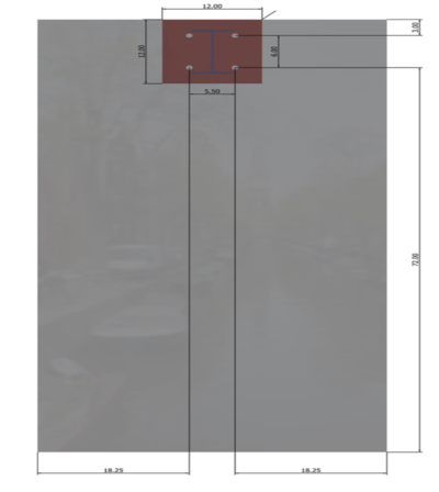
Figure 1: Design Dimensions for Example Embed Plate Design
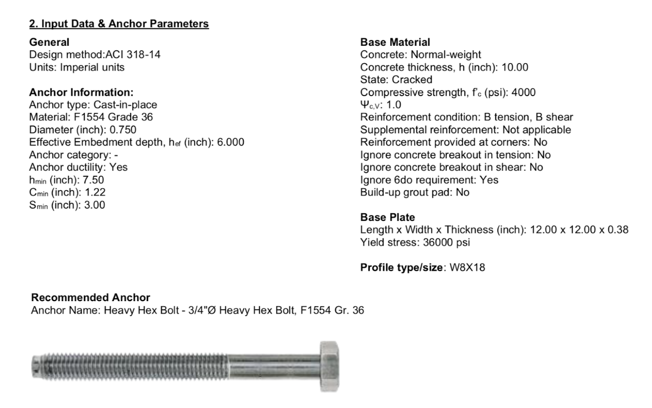
Figure 2: Input Data & Anchor Parameters for Example Embed Plate Design
Next, the load and geometry are added in to the design elements. The concrete, embed plate, and anchor design was analyzed with no seismic loading or tension to simulate a standard gravity connection of a steel beam to concrete wall. The output of the design loads and geometry can be found in Figure 3, and the image of the design with forces and moments can be found in Figure 4.
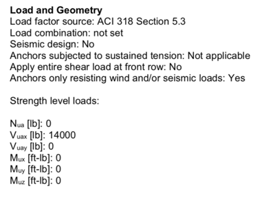
Figure 3: Load and Geometry for Example Embed Plate Design
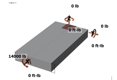
Figure 4: Software Generated Image of Design for Example Embed Plate Design
The figure shows a 14,000 lbs shear force along the x-axis with no forces along the z-axis or y-axis.

Next the four anchors and their forces are outputted by the system. In Figure 5, the four anchors can be seen on the embed plate with correct labels and placement. Each anchor showed no tension load or shear load in the y-axis and each anchor had the same shear load in x-axis. The shear load in x and shear combined load was 3,500 lbs for anchors 1, 2, 3, and 4. The sum of the shear loads in x-axis was 14,000 lbs, which matches the total shear load input. The output also calculated the concrete compression and tension forces, along with eccentricity of resultant forces. Figure 6 shows the output of these calculations, and Figure 7 shows the equations and calculations used for steel strength of anchor in shear, concrete breakout strength, shear parallel to edge in x-direction, and the concrete pryout strength.
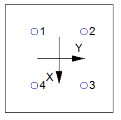
Figure 5: Anchor Placement on Embed Plate for Example Embed Plate Design
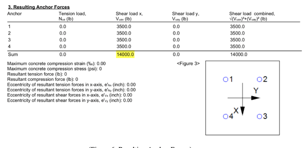
Figure 6: Resulting Anchor Forces for Example Embed Plate Design
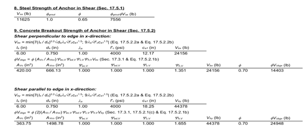
Figure 7: Steel Strength of Anchor in Shear, Concrete Breakout Strength of Anchor in Shear & Concrete Pryout Strength of Anchor in Shear for Example Embed Plate Design
The program used for the embed plate design provides the final results of the interaction of tensile and shear forces in the design. The highlighted areas indicate the governing interaction ratio. The governing ratio was calculated to be 0.97, which was less than the required 1.0 to be considered acceptable. Therefore, in this example the BEP-2 model embed plate design proved to be a valid design with a vertical shear load of 14,000 lbs based on the input values.

Figure 8: Overall Results for Example Embed Plate Design
The Simpson Strong-Tie Anchor Designer ™ Software is a software system used daily by professional engineers to test different anchor and embed plate designs. The embed plate design was accomplished using this well-known software and has been validated by full scale load testing with observed failure loads exceeding 600 times higher than the allowable loads of ACI-318, Chapter 17. Although EM-BOLT boltable embed plates are a new innovative technology, one should not fear innovation, but embrace the benefits that new technology can provide, while using a software that is commonly used and accepted by practicing structural engineers.
Interested in learning more about how EM-BOLT boltable embed plates save construction costs and time? Take advantage of the Guide below!
Would you like help with your concrete embedded plate engineering calculations? Reach out to us below.

Embedded plate Revit drawings of our standard series of products are also available, for Revit drawings go here.
To learn more about the advantages of EM-BOLT Boltable Embedded Plates, go here.
To learn more about our Concrete Slab Thermal Break solutions, go here.